Reverse engineering #2
Part of the fun of this job, as well as the frustration, is that I get some really weird and interesting pens to work on. The fun is that I get to figure things out. The frustration is that sometimes you look at a pen and realize that you have no clue how you’re going to do what needs to be done. You say “sure! I can do that.” Then when you start to work on the pen you say “how am I going to do that?” The pen below is a classic case in point.
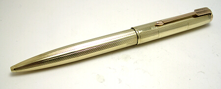
It’s a 14K “Parker 51”. I put quotes around it because those who should know say that Parker never made a 14K (as in solid gold) Parker 51. But it sure looks like one, but there a few weird elements as we’ll see. The client handed it to me at a pen show to install a 14K clip. It was an interesting pen because while it looked like a 51 and the mechanism was stock 51, the barrel and cap were much fatter. As I worked on the pen I noted other things that were, different, and told the owner that I’d do what I could, but that there was a good chance that we would have to do more extensive work on the cap. I simply didn’t have the tools or time at the show to correct the problems that I saw. I installed the clip as requested and handed the pen back. Sure enough, a couple of months later they contacted me and asked if they could send the pen to me because the clip had come loose. I stared at it when it came in and started to ask questions about how a 51 ballpoint was built. Finally I asked my friend Harry Shubin if he could send one of his original ballpoints to me for reference.
First, a correct 51. The clip on a ballpoint is the same size as a pencil, so smaller than the fountain pen’s clip. This is Harry’s Parker 51 with the jewel, clip screw and clip removed. Note that there is a tab that sticks up from the mechanism AND the cap to keep the clip from rotating, and that the mechanism pokes through the top of the cap. There is also a shoulder on the mechanism that the clip fits over to keep it centered on the cap. The big problem is that the gold pen’s cap is much larger than the stock cap so the mechanism fell right through the top. The clip is fatter because it’s not a ballpoint clip but a fountain pen clip. Fun.
With the mechanism removed from the stock 51, we can see that there is a lip that the mechanism fits under that keeps the mechanism from poking through the top.
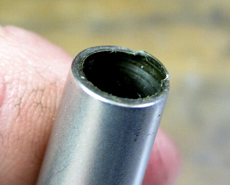
The original mechanism also has a flange on it that sits below the lip on the cap. The clip, held in place by the clip screw, and that clamps everything together. Note too that when the cap is pressed down, the whole mechanism goes down, stopping just before the flange hits the tube below. That’s important as we will see later.
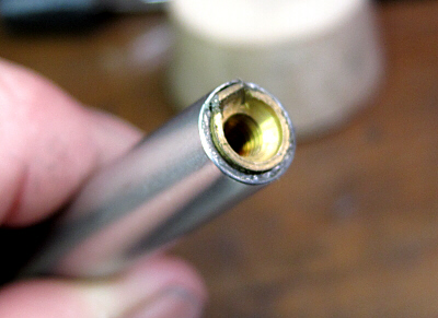
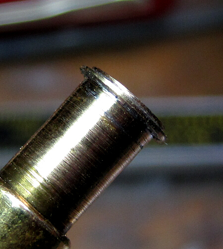
This is what the top of the gold cap looked like. Do you see what’s missing?

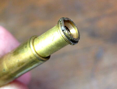
And the gold 51 mechanism.
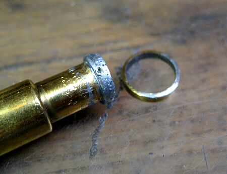
What is missing from the cap of course is the lip that keeps the mechanism from going through. To try to compensate, someone had soldered a brass ring onto the top of the mechanism. Nice idea, but it didn’t work. One problem was that they used ordinary solder – along the lines of 60/40 solder or plumbing solder which doesn’t have the strength of silver bearing solder or silver solder. The second problem was that it was simply too thin. While it was supposed to stop in the cap, it didn’t but wanted to slip right through, which was the problem that I saw when I first worked on the pen. Eventually it did slip through, which is why it came back to me.
The first step then was to clean off all of the solder and return the mechanism to it’s original configuration.
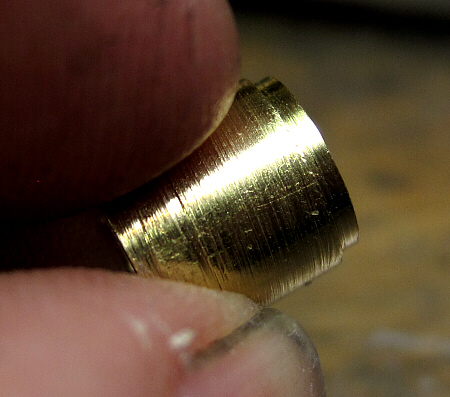
Now, how to fit it into the pen. You don’t see it when you look at the cap in the picture above, but there is taper to the top of the cap. The solution then was to take advantage of this taper, which is what they tried to do with the original setup. But their ring was too short, so the taper didn’t “jam” into the cap as it needed to. Staying with brass, which is strong and easier to machine, I used rod stock that was the same diameter as the opening of the cap, and then tapered it so that just a bit stuck out the top. The piece stopped against the taper with just a bit sticking beyond the cap. I then machined a step into the top like the mechanism has for the clip to slip over. The easy part was done.
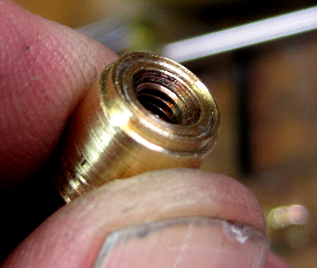
The inside was a bit trickier. I needed two steps. One for the flange to stop against, and another to center the flange. The ID of the sleeve had to be larger than the flange because the sleeve had to clear the body of the mechanism, which is wider than the flange. No doubt this is why the the last person to work on the pen had used a thinner ring. A bit tricky, and took a lot of careful measuring, but it worked.

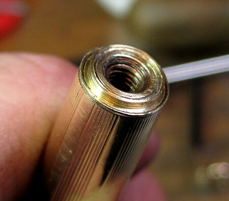
Here’s a picture of the sleeve on the mechanism. It slips freely over the body of the mechanism.
![]()
The top of the sleeve with the mechanism inside. The top of the mechanism is just a bit below the end of the sleeve.
And finally, with the cap in place
Alignment of the parts proved to be critical, but when aligned and the clip screw tightened down, it all held securely. No adhesives used or soldering done. In theory at least, the owner could slip in a standard mechanism should this one fail with the only modification the removal of the tab that holds the clip in place. The end result is of course the picture at the top.
I only scrapped out once. Total time involved? More than I would like, but less than it could have been. Satisfaction of both ends (mine and the owners)? Quite high, thank you!
Tags: 51 ballpoint repair, custom pen repair, gold Parker 51 repair, reverse engineering